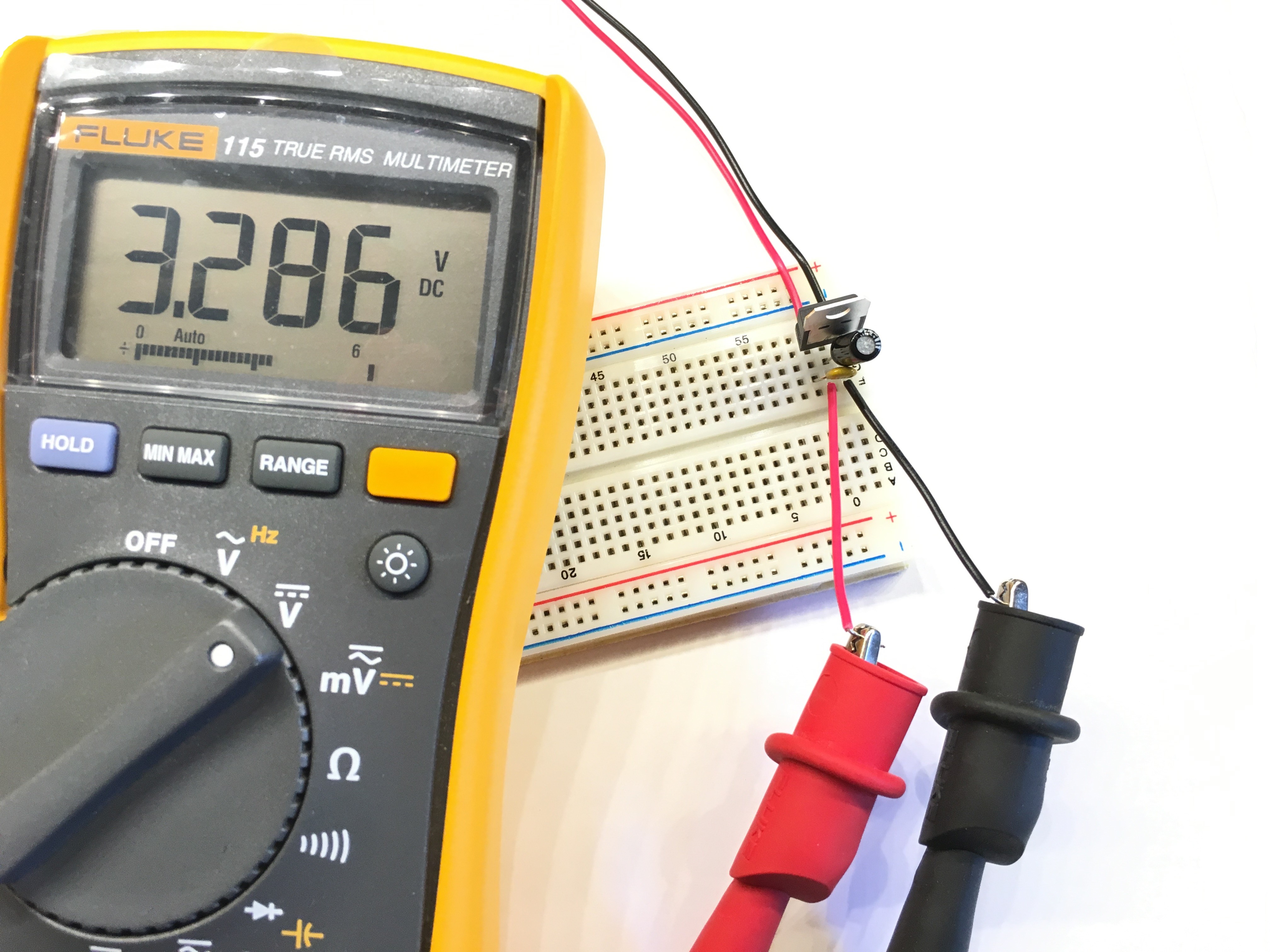
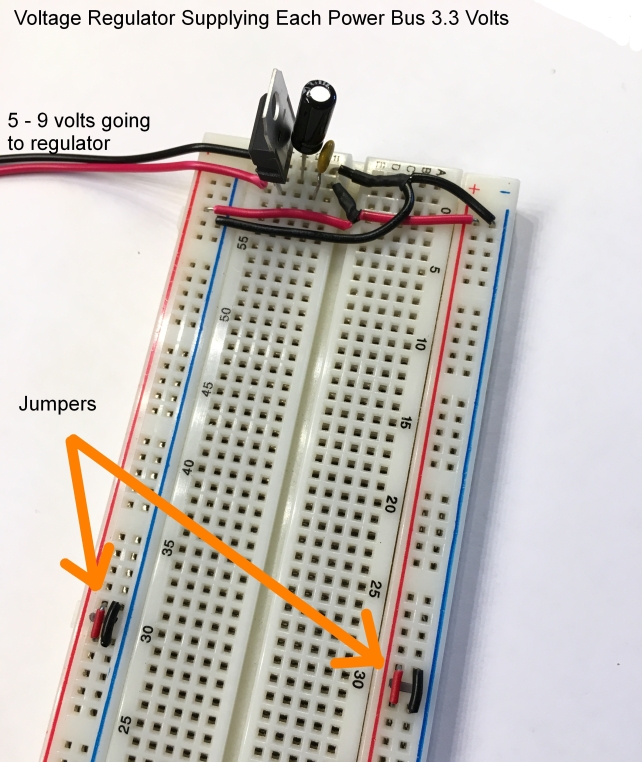
The traditional 'Hello World' project for any microcontroller is the blinking of an LED, and far be it from me to break from tradition, so that's what this article will describe. Please refer to the images and schematic drawings at the bottom of this webpage for details since this article is simply a cursory overview of how to blink an LED using a PIC and not a step-by-step guide. I'm assuming the reader has some knowledge tinkering with electronics. If you're a true tinkerer, you already have a spare breadboard, resistors, LEDs and other tinker supplies, but probably don't have a PIC18F45K22 or a PIC programmer which is required to get your code into the microcontroller. I recommend a PICkit 3 in-circuit programmer. With a PICkit3 you can program most PIC16 and PIC18 microcontrollers. So go get these and come back to this article. One nice thing about the PIC18F45K22 is that it can be operated with as little as 2.3 volts. This is good, since it allows you to use the PIC18 along side other devices that require about 3.3 volts, such as the ESP8266-01 wifi module. The first thing you must do is decide on what the input voltage is going to be for your PIC - input range is 2.3 - 5.5 volts. Setup your breadboard with a voltage regulator, a 7805 if you're going to feed the PIC18 5 volts or a LM1117T if you want to power your PIC with 3.3 volts. I placed smoothing capacitors in the voltage regulator circuit to ensure a nice even voltage flow into the PIC18, but often the voltage regulator datasheet mentions that this is not necessary. Be sure to use a multi-meter to check the output of the voltage regulator once everything is hooked up.

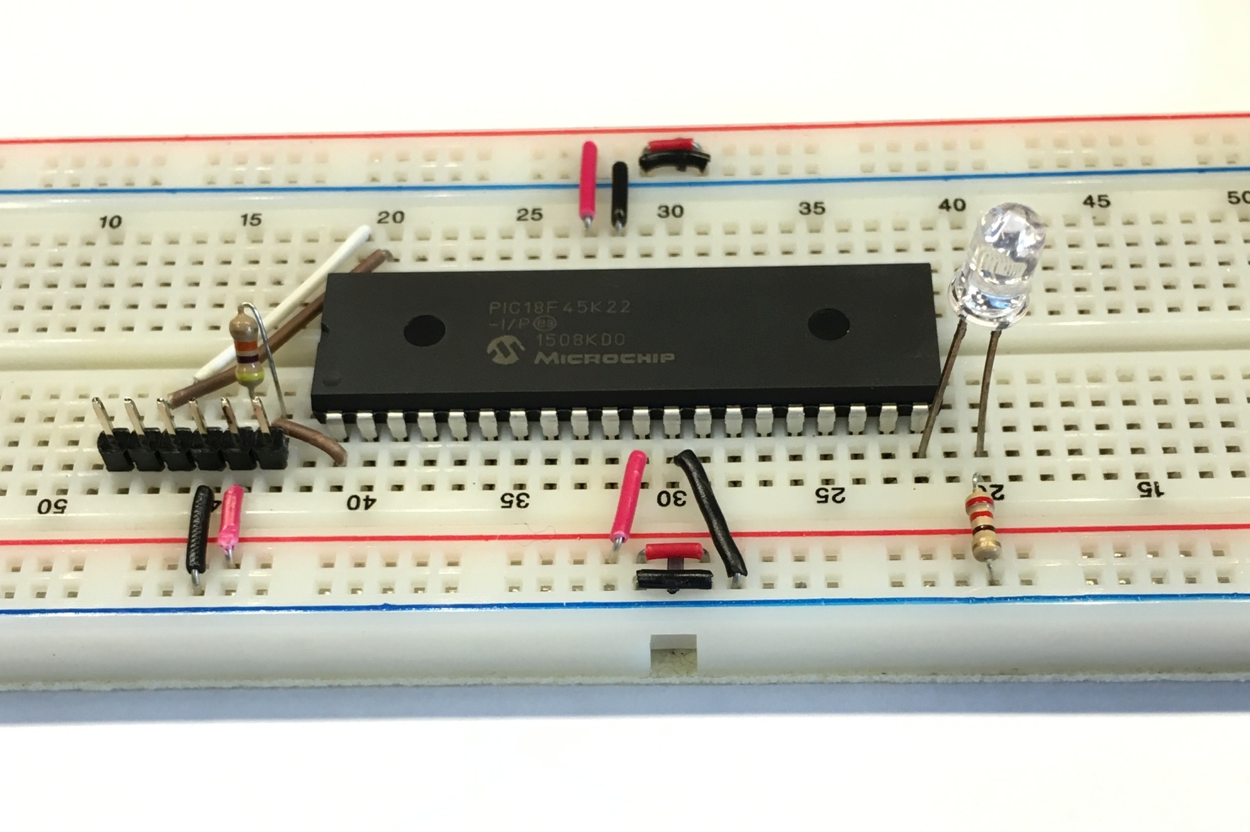
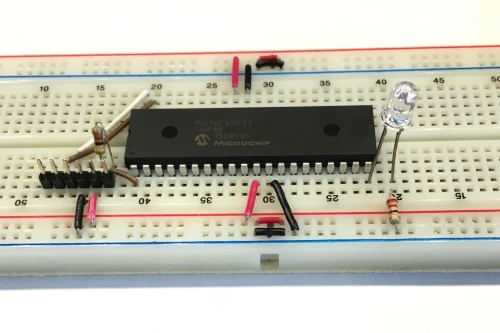
Once you are sure your supply voltage is correct, turn off the power and place the PIC18F45K22 on the center of the breadboard. The PIC18F45K22 is a 40 pin device and takes up alot of breadboard realestate so it's best to place it in a central location. Be very careful not to damage the pins when pressing the microcontroller into the breadboard. If you are afraid to damage the pins, I recommend purchasing a 40 pin socket and placing that into the breadboard so the PIC18 devices can be interchanged easily once programmed. Hook up power and ground wires as shown in the schematic images. Pins 11 and 32 go to the power bus on the breadboard and pins 12 and 31 go to ground. This article assumes you are using a PIC18F45K22 microcontroller. Check the datasheet of your microcontroller to be sure you are connecting power and ground correctly. Next, connect a LED and resistor to pin 20 (RD1) of the PIC18 as shown in the schematic. The resistor is connected between the cathode of the LED and ground. I used a 220 ohm resistor which is more than enough considering the LED I chose and the 3.3 voltage. If you're not sure refer to the datasheet of the LED you are using. Look for the forward voltage and forward current in the datasheet and use the formula R = (Vs - Vf) / If, where Vs is the supply voltage (3.3 in my project), Vf is the LED forward voltage, If is the LED forward current, and R is resistance. I calculated 65 ohms which is the minimum resistance I should use, so I went with a 220 ohm resistor since I had one handy. That's all for this simple project - well, not exactly.
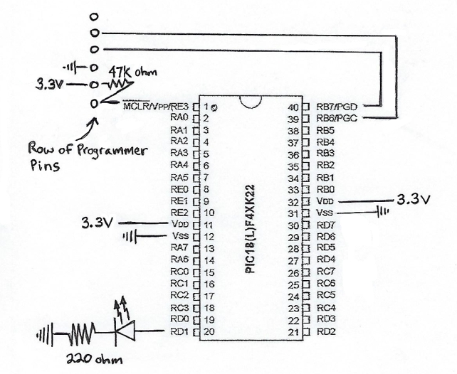
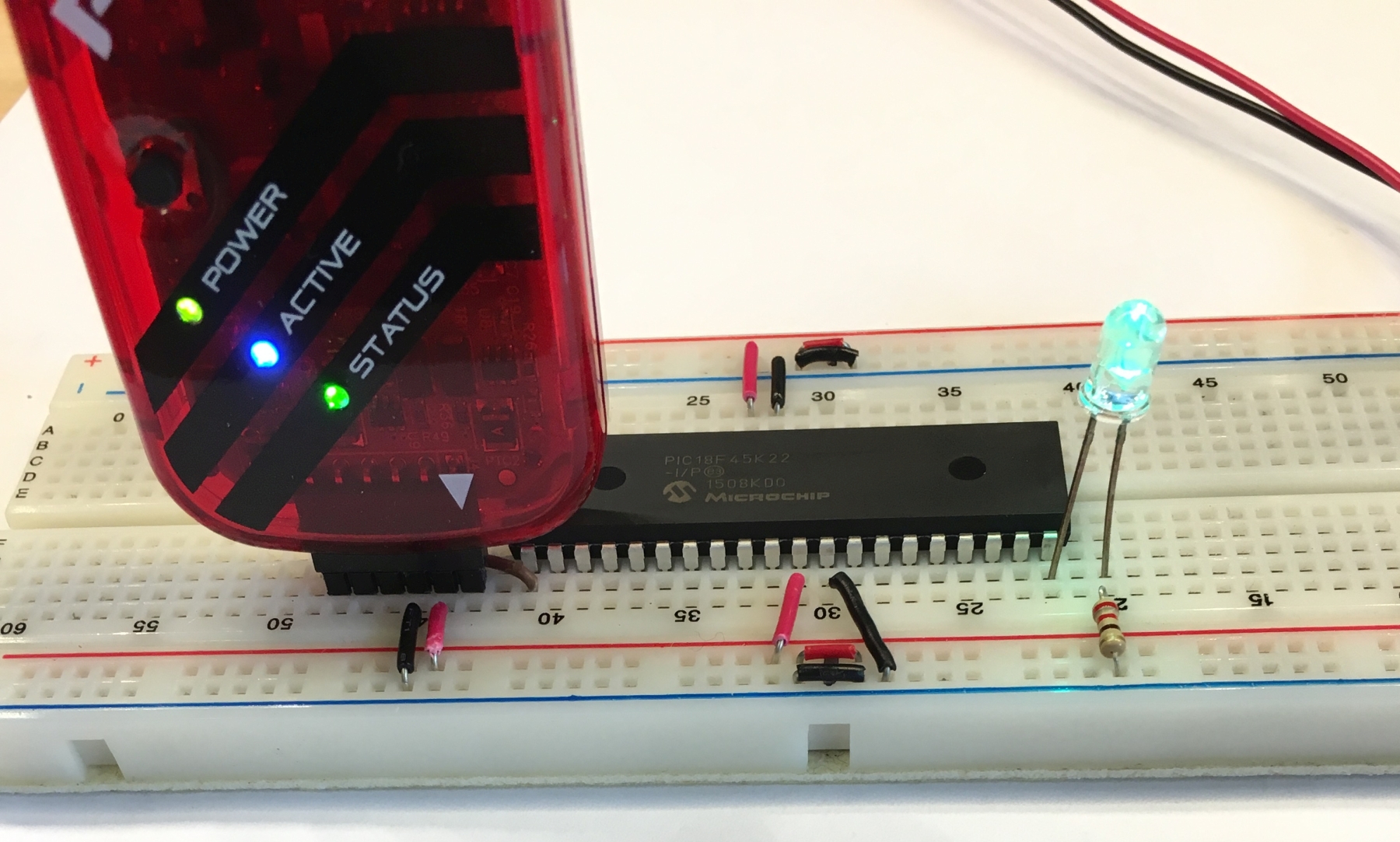
As is, the microcontroller does nothing. It needs to be programmed to blink the LED. You can purchase a PIC development board kit that comes with a PIC programmer, but they are not cheap. Or purchase just a PICkit 3 in-circuit programmer and program the PIC in-place. By adding just a few more items to the breadboard, you can program the PIC without removing it from the breadboard. Add the 6-pin header (0.100" spacing) and a 47K Ohm resistor to the breadboard as shown in the schematic. When connecting the PICkit 3 programmer to the header pins, be sure to align the pin 1 indicator (the triangle icon) on the Programmer to the pin 1 header pin which is the pin that connects to pin 1 (MCLR/Vpp) on the PIC.
Microchip Technology Inc. offers a free development environment to code PIC projects in called MPLAB X IDE. This new version of MPLAB is a huge improvement from the earlier versions and is based on the Netbeans IDE. It can be downloaded from the Microchip website at http://www.microchip.com/mplab/mplab-x-ide. You will also need a C compiler to compile the source code you write in the IDE. Microchip offers a free to use, (in non-optimised mode) C compiler, which is fine for most simple PIC projects called XC8. MPLAB and XC8 work well together. XC8 can be downloaded here: http://www.microchip.com/mplab/compilers. If you have never developed any PIC projects before, you may want to review the 'Getting Started' info located on the Microchip wiki here: http://microchip.wikidot.com/tls0101:start
Start a new project in the MPLAB IDE, add a new C source file and type or copy the following code into the project.
/***********************************************

 * Microcontroller used is the PIC18F45K22

 * Compiler used is XC8 VERSION 1.35

 * This program blinks an LED

 ****************************/

#include < xc.h >


#pragma config FOSC = INTIO67   // Oscillator Selection bits (Internal oscillator block)

#pragma config MCLRE = EXTMCLR  // MCLR pin enabled, RE3 input pin disabled

#pragma config WDTEN = OFF      // Watchdog Timer Enable bits (Set to disable Watchdog timer)


#define _XTAL_FREQ 16000000  //speed of the internal oscillator


/*IRCF<2:0> Set Up Internal RC Oscillator Frequency Select bits

 * 111 = HFINTOSC - (16 MHz) SEE PAGE 32 OF DATASHEET

 */

void SetUpClock(){

    OSCCONbits.IRCF0 = 1;

    OSCCONbits.IRCF1 = 1;

    OSCCONbits.IRCF2 = 1;

}


/* Creates delay in seconds

 * parameter s is the number of seconds */

void delay_seconds(unsigned char s){

    unsigned char i,j;


    for(i = 0; i < s; i++)

    {

        for(j = 0; j < 100; j++)

            __delay_ms(10);

    }

}


//Flashes an LED at one second intervals

void FlashLEDs(){

    for(int i = 0;i < 2; i++)

    {

        PORTDbits.RD1 = 1;  //LED 1 ON

        delay_seconds(1);

        PORTDbits.RD1 = 0;  //LED 1 OFF

        delay_seconds(1);

    }

}


int main(){

    SetUpClock(); //internal clock set to 16MHz


    ANSELD = 0; //Configure PORTD as digital

    TRISD = 0; //Configure PORTD as output

    PORTD = 0b00000000; //initial state - PORTD all off


    for(;;){ //infinite loop

        FlashLEDs();

    }

}
As you can see the program is coded in C. All the microcontroller setup code makes it look more complicated than it really is. There is a function called FlashLEDs that is called from within an infinite loop that resides inside the main function. I'm using the internal oscillator of the microcontroller so there is no need to add a crystal to the circuit. The details of this code are outside the scope of this article. The main purpose of this article was to show that programming a PIC micro is not too difficult and to inspire people to break away from the more user-friendly microcontrollers by giving a PIC a try. I recommend downloading the datasheet for the PIC18F45K22 and studying it. Also, reading the XC8 users guide is recommended. All the documents you need to become familar with the PIC18F45K22 can be downloaded from the Microchip website. Additionally, I recommend purchasing the book, PIC Microcontroller Projects In C Basic To Advanced by Dogan Ibrahim. This book is very well written and can be purchased from Amazon.com. The learning curve to program the PIC series microcontrollers can be a bit steep, but once you have a few projects under your belt I'm sure you'll find that the PIC microcontrollers are worth the effort. The price point for these microcontrollers are such that you can create many gadgets and not go broke. That alone should be reason enough to consider learning to program this type of microcontroller.